Good Quality Rigid Flange Coupling - GE Couplings, Type 1/1, 1a/1a, 1b/1b in AL/Cast/Steel – GOODLUCK
Good Quality Rigid Flange Coupling - GE Couplings, Type 1/1, 1a/1a, 1b/1b in AL/Cast/Steel – GOODLUCK Detail:
GE COUPLINGS (AL, CAST)

|
GE(AL-H) |
|||||||||||||||||
|
ITEM |
PART |
(Nm) |
size(mm) |
||||||||||||||
|
d(min-max) |
Overall dimensions |
Set screw |
|||||||||||||||
|
92 Sh A |
98 Sh A |
64 Sh D |
L |
l1;l2 |
E |
b |
s |
DH |
dH |
D ; D1 |
N |
G |
t |
TA(Nm) |
|||
|
14 |
1a |
7.5 |
12.5 |
- |
6-16 |
35 |
11 |
13 |
10 |
1.5 |
30 |
10 |
30 |
- |
M4 |
5 |
1.5 |
|
19 |
1 |
10 |
17 |
- |
6-19 |
66 |
25 |
16 |
12 |
2 |
40 |
18 |
32 |
20 |
M5 |
10 |
2 |
|
1a |
19-24 |
40 |
|||||||||||||||
|
24 |
1 |
35 |
60 |
- |
9-24 |
78 |
30 |
18 |
14 |
2 |
55 |
27 |
40 |
24 |
M5 |
10 |
2 |
|
1a |
22-28 |
55 |
|||||||||||||||
|
28 |
1 |
95 |
160 |
- |
10-28 |
90 |
35 |
20 |
15 |
2.5 |
65 |
30 |
48 |
28 |
M8 |
15 |
10 |
|
1a |
28-38 |
65 |
|||||||||||||||
GE EN-GJL-250 ( GG 25 )
|
1 |
12-38 |
66 |
|||||||||||||||
|
38 |
1a |
190 |
325 |
405 |
38-45 |
114 |
45 |
24 |
18 |
3 |
80 |
38 |
37 |
M8 |
15 |
10 |
|
|
1b |
12-45 |
164 |
70 |
62 |
|||||||||||||
|
1 |
14-42 |
75 |
|||||||||||||||
|
42 |
1a |
265 |
450 |
560 |
42-55 |
126 |
50 |
26 |
20 |
3 |
95 |
46 |
94 |
40 |
M8 |
20 |
10 |
|
1b |
14-55 |
176 |
75 |
65 |
|||||||||||||
|
1 |
15-48 |
85 |
|||||||||||||||
|
48 |
1a |
310 |
525 |
655 |
48-60 |
140 |
56 |
28 |
21 |
3.5 |
105 |
51 |
45 |
M8 |
20 |
10 |
|
|
1b |
15-60 |
188 |
80 |
69 |
|||||||||||||
|
1 |
20-55 |
98 |
|||||||||||||||
|
55 |
1a |
410 |
685 |
825 |
55-70 |
160 |
65 |
30 |
22 |
4 |
120 |
60 |
118 |
M10 |
20 |
17 |
|
|
1b |
20-70 |
210 |
90 |
120 |
- |
||||||||||||
|
1 |
22-65 |
115 |
61 |
||||||||||||||
|
65 |
1a |
625 |
940 |
1175 |
65-80 |
185 |
75 |
35 |
26 |
4.5 |
135 |
68 |
M10 |
20 |
17 |
||
|
1b |
22-80 |
235 |
100 |
||||||||||||||
|
1 |
30-75 |
135 |
69 |
||||||||||||||
|
75 |
1a |
1280 |
1920 |
2400 |
75-95 |
210 |
85 |
40 |
30 |
5 |
160 |
80 |
1RQ |
M10 |
25 |
17 |
|
|
1b |
30-95 |
260 |
110 |
||||||||||||||
|
1 |
40-90 |
160 |
81 |
||||||||||||||
|
90 |
1a |
2400 |
3600 |
4500 |
90-110 |
245 |
100 |
45 |
34 |
5.5 |
200 |
100 |
M12 |
30 |
40 |
||
|
1b |
40-110 |
295 |
125 |
GE EN-GJL-400-15 ( GGg 40 )
|
100 |
1 |
3300 |
4950 |
6185 |
50-115 |
270 |
110 |
50 |
38 |
6 |
225 |
113 |
180 |
89 |
M12 |
30 |
40 |
|
110 |
1 |
4800 |
7200 |
9000 |
60-125 |
295 |
120 |
55 |
42 |
6.5 |
255 |
127 |
200 |
96 |
M16 |
35 |
80 |
|
125 |
1 |
6650 |
10000 |
12500 |
60-145 |
340 |
140 |
60 |
46 |
7 |
290 |
147 |
230 |
112 |
M16 |
40 |
80 |
|
140 |
1 |
8550 |
12800 |
16000 |
60-160 |
375 |
155 |
65 |
50 |
7.5 |
320 |
165 |
255 |
124 |
M20 |
45 |
140 |
|
160 |
1 |
12800 |
19200 |
24000 |
80-185 |
425 |
175 |
75 |
57 |
9 |
370 |
190 |
290 |
140 |
M20 |
50 |
140 |
|
180 |
1 |
18650 |
28000 |
35000 |
85-200 |
475 |
185 |
85 |
64 |
10.5 |
420 |
220 |
325 |
156 |
M20 |
50 |
140 |

|
GE (STEEL) |
|||||||||||||||||
|
ITEM |
PART |
(Nm) |
SIZE (mm) |
||||||||||||||
|
d(min-max) |
Overall dimensions |
Special dimensions of steel sleeve |
Set screw |
||||||||||||||
|
92 Sh A |
98 Sh A |
64 Sh D |
L |
E |
b |
s |
DH |
dh |
D;D1 |
N |
G |
t |
TA(Nm) |
||||
|
14 |
1a |
7.5 |
12.5 |
16 |
0-16 |
35 |
11 |
13 |
10 |
1.5 |
30 |
10 |
30 |
- |
M4 |
5 |
1.5 |
|
1b |
50 |
18.5 |
|||||||||||||||
|
19 |
1a |
10 |
17 |
21 |
0-25 |
66 |
25 |
16 |
12 |
2 |
40 |
18 |
40 |
M5 |
10 |
2 |
|
|
1b |
90 |
37 |
|||||||||||||||
|
24 |
1a |
35 |
60 |
75 |
0-35 |
78 |
30 |
18 |
14 |
2 |
55 |
27 |
55 |
M5 |
10 |
2 |
|
|
1b |
118 |
50 |
|||||||||||||||
|
28 |
1a |
95 |
160 |
200 |
0-40 |
90 |
35 |
20 |
15 |
2.5 |
65 |
30 |
65 |
- |
M8 |
15 |
10 |
|
1b |
140 |
60 |
|||||||||||||||
|
38 |
1 |
190 |
325 |
405 |
0-48 |
114 |
45 |
24 |
18 |
3 |
80 |
38 |
70 |
27 |
M8 |
15 |
10 |
|
1b |
164 |
70 |
85 |
- |
|||||||||||||
|
42 |
1 |
265 |
450 |
560 |
0-55 |
126 |
50 |
26 |
20 |
3 |
95 |
46 |
85 |
28 |
M8 |
20 |
10 |
|
1b |
176 |
75 |
95 |
- |
|||||||||||||
|
48 |
1 |
310 |
525 |
655 |
0-62 |
140 |
56 |
28 |
21 |
3.5 |
105 |
51 |
95 |
32 |
M8 |
20 |
10 |
|
1b |
188 |
80 |
105 |
- |
|||||||||||||
|
55 |
1 |
410 |
685 |
825 |
0-74 |
160 |
65 |
30 |
22 |
4 |
120 |
60 |
110 |
37 |
M10 |
20 |
17 |
|
1b |
210 |
90 |
120 |
- |
|||||||||||||
|
65 |
1 |
625 |
940 |
1175 |
0-80 |
185 |
75 |
35 |
26 |
4.5 |
135 |
68 |
115 |
47 |
M10 |
20 |
17 |
|
1b |
235 |
100 |
135 |
- |
|||||||||||||
|
75 |
1 |
1280 |
1920 |
2400 |
0-95 |
210 |
85 |
40 |
30 |
5 |
160 |
80 |
135 |
53 |
M10 |
25 |
17 |
|
1b |
260 |
110 |
160 |
- |
|||||||||||||
|
90 |
1 |
2400 |
3600 |
4500 |
0-110 |
245 |
100 |
45 |
34 |
5.5 |
200 |
100 |
160 |
62 |
M12 |
30 |
40 |
|
1b |
295 |
125 |
200 |
- |
|||||||||||||

GE(GG25)
|
ITEM |
TB |
size(mm) |
Mounting screw of shaft sleeve |
|||||||||||
|
l1;l2 |
E |
S |
b |
L |
N |
DH |
D1 |
dH |
Specification |
length |
number |
TA (Nm) |
||
|
24 |
1008 |
23 |
18 |
2.0 |
14 |
64 |
一 |
55 |
55 |
27 |
1/4 |
13 |
2 |
5.7 |
|
28 |
1108 |
23 |
20 |
2.5 |
15 |
66 |
一 |
65 |
65 |
30 |
1/4” |
13 |
2 |
5.7 |
|
38 |
1108 |
23 |
24 |
3.0 |
18 |
70 |
15 |
80 |
78 |
38 |
1/4” |
13 |
2 |
5.7 |
|
42 |
1610 |
26 |
26 |
3.0 |
20 |
78 |
16 |
95 |
94 |
46 |
3/8” |
16 |
2 |
20 |
|
48 |
1615 |
39 |
28 |
3.5 |
21 |
106 |
28 |
105 |
104 |
51 |
3/8“ |
16 |
2 |
20 |
|
55 |
2012 |
33 |
30 |
4.0 |
22 |
96 |
20 |
120 |
118 |
60 |
7/16” |
22 |
2 |
31 |
|
65 |
2012 |
33 |
35 |
4.5 |
26 |
101 |
19 |
135 |
115 |
68 |
7/16” |
22 |
2 |
31 |
|
2517 |
1/2” |
25 |
49 |
|||||||||||
|
75 |
. 3020 |
52 |
40 |
5.0 |
30 |
144 |
36 |
160 |
158 |
80 |
5/8″ |
32 |
2 |
92 |
|
90 |
3020 |
52 |
45 |
5.5 |
24 |
144 |
33 |
200 |
160 |
100 |
5/8“ |
32 |
2 |
92 |
|
125 |
3535 |
90 |
60 |
147 |
1/2” |
3 |
113 |
|||||||
|
4545 |
114 |
3/4″ |
49 |
192 |
||||||||||
*ONLY FOR H TYPE *BSW SCREW
|
Cone sleeve |
|||||||||||||||||||
|
Specification |
The tolerance of finished hole diameter D1 can be H7 keyway according to DIN 6885 / 1 |
||||||||||||||||||
|
1008 |
10 |
11 |
12 |
14 |
16 |
18 |
19 |
20 |
22 |
24 |
25 |
||||||||
|
1108 |
10 |
11 |
12 |
14 |
16 |
18 |
19 |
20 |
22 |
24 |
25 |
28* |
|||||||
|
1610 |
14 |
16 |
18 |
19 |
20 |
22 |
24 |
25 |
28 |
30 |
32 |
35 |
38 |
40 |
42* |
||||
|
1615 |
14 |
16 |
18 |
19 |
20 |
22 |
24 |
25 |
28 |
30 |
32 |
35 |
38 |
40 |
42* |
||||
|
2012 |
14 |
16 |
18 |
19 |
20 |
22 |
24 |
25 |
28 |
30 |
32 |
35 |
38 |
40 |
42 |
45 |
48 |
50 |
|
|
2517 |
16 |
18 |
19 |
20 |
22 |
24 |
25 |
28 |
30 |
32 |
35 |
38 |
40 |
42 |
45 |
48 |
50 |
55 |
60 |
|
3020 |
25 |
28 |
30 |
35 |
38 |
40 |
42 |
45 |
48 |
50 |
55 |
60 |
65 |
70 |
75 |
||||
|
3535 |
35 |
38 |
40 |
42 |
45 |
48 |
50 |
55 |
60 |
65 |
70 |
75 |
80 |
85 |
90 |
||||
|
4545 |
55 |
60 |
65 |
70 |
75 |
80 |
85 |
90 |
95 |
100 |
105 |
110 |
|||||||
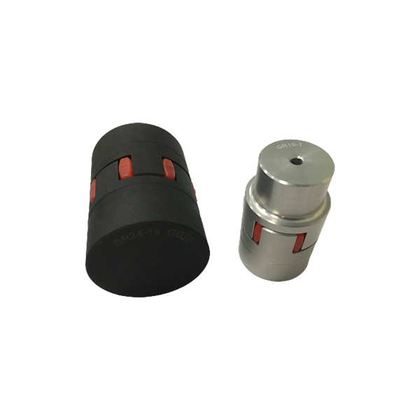
GL GE couplings are designed to transmit torque between drive and driven components with zero‑backlash via curved jaw hubs and elastomeric elements, commonly known as spiders. The combination of these components provides dampening and accommodation of misalignment. This product is available in a variety of metals, elastomers and mounting configurations to meet your specific needs. GL GS couplings suitable for horizontal or vertical applications are constructed from a variety of materials, providing a torsionally flexible zero‑backlash platform optimizing the balance between inertia, coupling performance and application requirements. The machined concaved jaws provide a pocket to preload the spider legs, allowing the spiders to articulate freely while accommodating misalignment, minimizing restoring forces, dampen shock and vibration, while providing failsafe zero‑backlash torque transmission. The symmetrical relationship of the hubs allows for a variety of accessories to accommodate different shaft distances.
Product detail pictures:
Related Product Guide:
Being supported by an state-of-the-art and skilled IT team, we could supply technical support on pre-sales & after-sales service for Good Quality Rigid Flange Coupling - GE Couplings, Type 1/1, 1a/1a, 1b/1b in AL/Cast/Steel – GOODLUCK , The product will supply to all over the world, such as: Angola, Czech republic, Algeria, We've a skilled sales team, they have mastered the best technology and manufacturing processes, have years of experience in foreign trade sales, with customers able to communicate seamlessly and accurately understand the real needs of customers, providing customers with personalized service and unique merchandise.
The sales manager is very patient, we communicated about three days before we decided to cooperate, finally, we are very satisfied with this cooperation!
-
PriceList for Stainless Steel Short Pitch Conve...
-
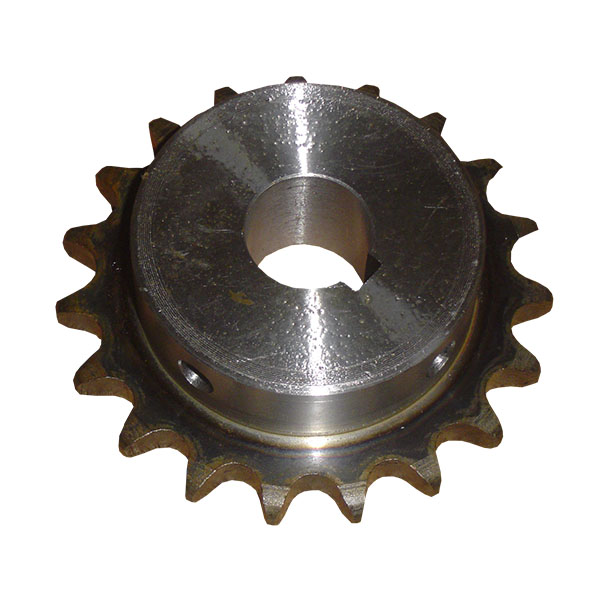
2021 wholesale price Double Sprockets For Two S...
-
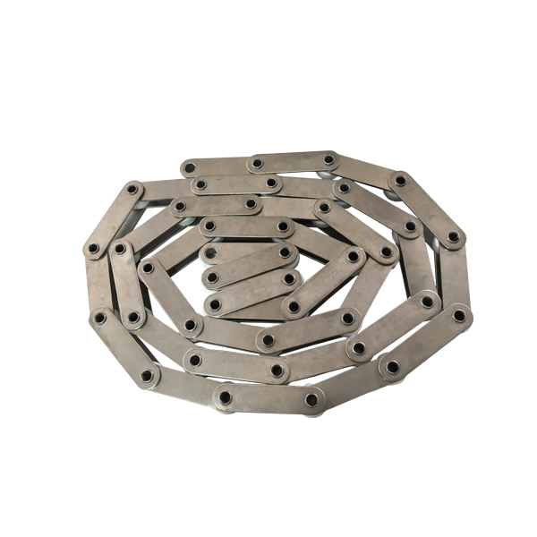
100% Original Stainless Steel Fv Series Conveyo...
-
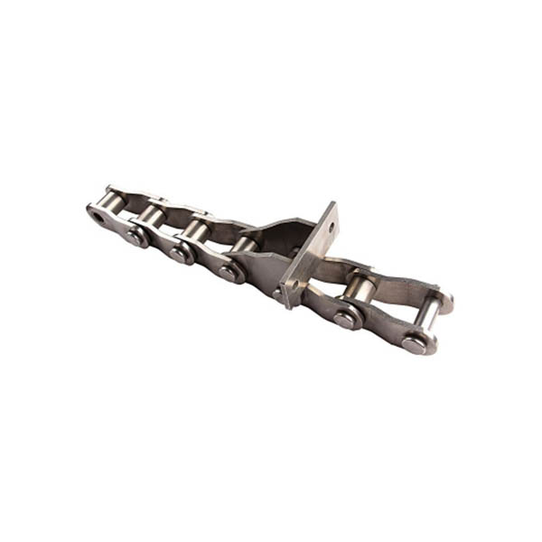
Reliable Supplier Flat Chain Conveyor - Welded...
-
Reliable Supplier O Ring Motorcycle Chain - Of...
-
Factory supplied Disc Coupling - Weld-On-Hubs,...