Popular Design for Mct Couplings - GE Couplings, Type 1/1, 1a/1a, 1b/1b in AL/Cast/Steel – GOODLUCK
Popular Design for Mct Couplings - GE Couplings, Type 1/1, 1a/1a, 1b/1b in AL/Cast/Steel – GOODLUCK Detail:
GE COUPLINGS (AL, CAST)

|
GE(AL-H) |
|||||||||||||||||
|
ITEM |
PART |
(Nm) |
size(mm) |
||||||||||||||
|
d(min-max) |
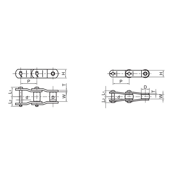
Overall dimensions |
Set screw |
|||||||||||||||
|
92 Sh A |
98 Sh A |
64 Sh D |
L |
l1;l2 |
E |
b |
s |
DH |
dH |
D ; D1 |
N |
G |
t |
TA(Nm) |
|||
|
14 |
1a |
7.5 |
12.5 |
- |
6-16 |
35 |
11 |
13 |
10 |
1.5 |
30 |
10 |
30 |
- |
M4 |
5 |
1.5 |
|
19 |
1 |
10 |
17 |
- |
6-19 |
66 |
25 |
16 |
12 |
2 |
40 |
18 |
32 |
20 |
M5 |
10 |
2 |
|
1a |
19-24 |
40 |
|||||||||||||||
|
24 |
1 |
35 |
60 |
- |
9-24 |
78 |
30 |
18 |
14 |
2 |
55 |
27 |
40 |
24 |
M5 |
10 |
2 |
|
1a |
22-28 |
55 |
|||||||||||||||
|
28 |
1 |
95 |
160 |
- |
10-28 |
90 |
35 |
20 |
15 |
2.5 |
65 |
30 |
48 |
28 |
M8 |
15 |
10 |
|
1a |
28-38 |
65 |
|||||||||||||||
GE EN-GJL-250 ( GG 25 )
|
1 |
12-38 |
66 |
|||||||||||||||
|
38 |
1a |
190 |
325 |
405 |
38-45 |
114 |
45 |
24 |
18 |
3 |
80 |
38 |
37 |
M8 |
15 |
10 |
|
|
1b |
12-45 |
164 |
70 |
62 |
|||||||||||||
|
1 |
14-42 |
75 |
|||||||||||||||
|
42 |
1a |
265 |
450 |
560 |
42-55 |
126 |
50 |
26 |
20 |
3 |
95 |
46 |
94 |
40 |
M8 |
20 |
10 |
|
1b |
14-55 |
176 |
75 |
65 |
|||||||||||||
|
1 |
15-48 |
85 |
|||||||||||||||
|
48 |
1a |
310 |
525 |
655 |
48-60 |
140 |
56 |
28 |
21 |
3.5 |
105 |
51 |
45 |
M8 |
20 |
10 |
|
|
1b |
15-60 |
188 |
80 |
69 |
|||||||||||||
|
1 |
20-55 |
98 |
|||||||||||||||
|
55 |
1a |
410 |
685 |
825 |
55-70 |
160 |
65 |
30 |
22 |
4 |
120 |
60 |
118 |
M10 |
20 |
17 |
|
|
1b |
20-70 |
210 |
90 |
120 |
- |
||||||||||||
|
1 |
22-65 |
115 |
61 |
||||||||||||||
|
65 |
1a |
625 |
940 |
1175 |
65-80 |
185 |
75 |
35 |
26 |
4.5 |
135 |
68 |
M10 |
20 |
17 |
||
|
1b |
22-80 |
235 |
100 |
||||||||||||||
|
1 |
30-75 |
135 |
69 |
||||||||||||||
|
75 |
1a |
1280 |
1920 |
2400 |
75-95 |
210 |
85 |
40 |
30 |
5 |
160 |
80 |
1RQ |
M10 |
25 |
17 |
|
|
1b |
30-95 |
260 |
110 |
||||||||||||||
|
1 |
40-90 |
160 |
81 |
||||||||||||||
|
90 |
1a |
2400 |
3600 |
4500 |
90-110 |
245 |
100 |
45 |
34 |
5.5 |
200 |
100 |
M12 |
30 |
40 |
||
|
1b |
40-110 |
295 |
125 |
GE EN-GJL-400-15 ( GGg 40 )
|
100 |
1 |
3300 |
4950 |
6185 |
50-115 |
270 |
110 |
50 |
38 |
6 |
225 |
113 |
180 |
89 |
M12 |
30 |
40 |
|
110 |
1 |
4800 |
7200 |
9000 |
60-125 |
295 |
120 |
55 |
42 |
6.5 |
255 |
127 |
200 |
96 |
M16 |
35 |
80 |
|
125 |
1 |
6650 |
10000 |
12500 |
60-145 |
340 |
140 |
60 |
46 |
7 |
290 |
147 |
230 |
112 |
M16 |
40 |
80 |
|
140 |
1 |
8550 |
12800 |
16000 |
60-160 |
375 |
155 |
65 |
50 |
7.5 |
320 |
165 |
255 |
124 |
M20 |
45 |
140 |
|
160 |
1 |
12800 |
19200 |
24000 |
80-185 |
425 |
175 |
75 |
57 |
9 |
370 |
190 |
290 |
140 |
M20 |
50 |
140 |
|
180 |
1 |
18650 |
28000 |
35000 |
85-200 |
475 |
185 |
85 |
64 |
10.5 |
420 |
220 |
325 |
156 |
M20 |
50 |
140 |

|
GE (STEEL) |
|||||||||||||||||
|
ITEM |
PART |
(Nm) |
SIZE (mm) |
||||||||||||||
|
d(min-max) |
Overall dimensions |
Special dimensions of steel sleeve |
Set screw |
||||||||||||||
|
92 Sh A |
98 Sh A |
64 Sh D |
L |
E |
b |
s |
DH |
dh |
D;D1 |
N |
G |
t |
TA(Nm) |
||||
|
14 |
1a |
7.5 |
12.5 |
16 |
0-16 |
35 |
11 |
13 |
10 |
1.5 |
30 |
10 |
30 |
- |
M4 |
5 |
1.5 |
|
1b |
50 |
18.5 |
|||||||||||||||
|
19 |
1a |
10 |
17 |
21 |
0-25 |
66 |
25 |
16 |
12 |
2 |
40 |
18 |
40 |
M5 |
10 |
2 |
|
|
1b |
90 |
37 |
|||||||||||||||
|
24 |
1a |
35 |
60 |
75 |
0-35 |
78 |
30 |
18 |
14 |
2 |
55 |
27 |
55 |
M5 |
10 |
2 |
|
|
1b |
118 |
50 |
|||||||||||||||
|
28 |
1a |
95 |
160 |
200 |
0-40 |
90 |
35 |
20 |
15 |
2.5 |
65 |
30 |
65 |
- |
M8 |
15 |
10 |
|
1b |
140 |
60 |
|||||||||||||||
|
38 |
1 |
190 |
325 |
405 |
0-48 |
114 |
45 |
24 |
18 |
3 |
80 |
38 |
70 |
27 |
M8 |
15 |
10 |
|
1b |
164 |
70 |
85 |
- |
|||||||||||||
|
42 |
1 |
265 |
450 |
560 |
0-55 |
126 |
50 |
26 |
20 |
3 |
95 |
46 |
85 |
28 |
M8 |
20 |
10 |
|
1b |
176 |
75 |
95 |
- |
|||||||||||||
|
48 |
1 |
310 |
525 |
655 |
0-62 |
140 |
56 |
28 |
21 |
3.5 |
105 |
51 |
95 |
32 |
M8 |
20 |
10 |
|
1b |
188 |
80 |
105 |
- |
|||||||||||||
|
55 |
1 |
410 |
685 |
825 |
0-74 |
160 |
65 |
30 |
22 |
4 |
120 |
60 |
110 |
37 |
M10 |
20 |
17 |
|
1b |
210 |
90 |
120 |
- |
|||||||||||||
|
65 |
1 |
625 |
940 |
1175 |
0-80 |
185 |
75 |
35 |
26 |
4.5 |
135 |
68 |
115 |
47 |
M10 |
20 |
17 |
|
1b |
235 |
100 |
135 |
- |
|||||||||||||
|
75 |
1 |
1280 |
1920 |
2400 |
0-95 |
210 |
85 |
40 |
30 |
5 |
160 |
80 |
135 |
53 |
M10 |
25 |
17 |
|
1b |
260 |
110 |
160 |
- |
|||||||||||||
|
90 |
1 |
2400 |
3600 |
4500 |
0-110 |
245 |
100 |
45 |
34 |
5.5 |
200 |
100 |
160 |
62 |
M12 |
30 |
40 |
|
1b |
295 |
125 |
200 |
- |
|||||||||||||

GE(GG25)
|
ITEM |
TB |
size(mm) |
Mounting screw of shaft sleeve |
|||||||||||
|
l1;l2 |
E |
S |
b |
L |
N |
DH |
D1 |
dH |
Specification |
length |
number |
TA (Nm) |
||
|
24 |
1008 |
23 |
18 |
2.0 |
14 |
64 |
一 |
55 |
55 |
27 |
1/4 |
13 |
2 |
5.7 |
|
28 |
1108 |
23 |
20 |
2.5 |
15 |
66 |
一 |
65 |
65 |
30 |
1/4” |
13 |
2 |
5.7 |
|
38 |
1108 |
23 |
24 |
3.0 |
18 |
70 |
15 |
80 |
78 |
38 |
1/4” |
13 |
2 |
5.7 |
|
42 |
1610 |
26 |
26 |
3.0 |
20 |
78 |
16 |
95 |
94 |
46 |
3/8” |
16 |
2 |
20 |
|
48 |
1615 |
39 |
28 |
3.5 |
21 |
106 |
28 |
105 |
104 |
51 |
3/8“ |
16 |
2 |
20 |
|
55 |
2012 |
33 |
30 |
4.0 |
22 |
96 |
20 |
120 |
118 |
60 |
7/16” |
22 |
2 |
31 |
|
65 |
2012 |
33 |
35 |
4.5 |
26 |
101 |
19 |
135 |
115 |
68 |
7/16” |
22 |
2 |
31 |
|
2517 |
1/2” |
25 |
49 |
|||||||||||
|
75 |
. 3020 |
52 |
40 |
5.0 |
30 |
144 |
36 |
160 |
158 |
80 |
5/8″ |
32 |
2 |
92 |
|
90 |
3020 |
52 |
45 |
5.5 |
24 |
144 |
33 |
200 |
160 |
100 |
5/8“ |
32 |
2 |
92 |
|
125 |
3535 |
90 |
60 |
147 |
1/2” |
3 |
113 |
|||||||
|
4545 |
114 |
3/4″ |
49 |
192 |
||||||||||
*ONLY FOR H TYPE *BSW SCREW
|
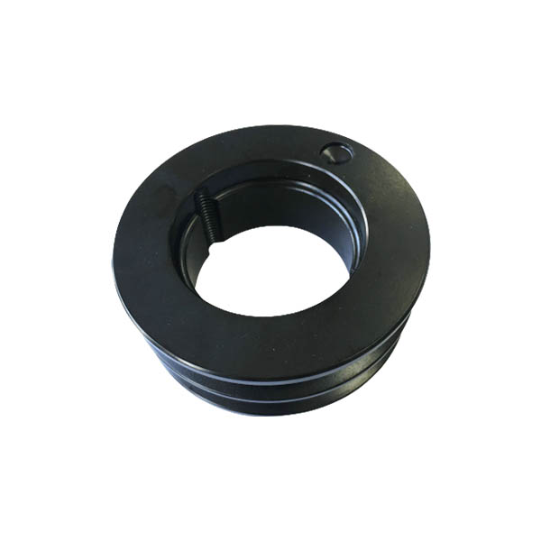
Cone sleeve |
|||||||||||||||||||
|
Specification |
The tolerance of finished hole diameter D1 can be H7 keyway according to DIN 6885 / 1 |
||||||||||||||||||
|
1008 |
10 |
11 |
12 |
14 |
16 |
18 |
19 |
20 |
22 |
24 |
25 |
||||||||
|
1108 |
10 |
11 |
12 |
14 |
16 |
18 |
19 |
20 |
22 |
24 |
25 |
28* |
|||||||
|
1610 |
14 |
16 |
18 |
19 |
20 |
22 |
24 |
25 |
28 |
30 |
32 |
35 |
38 |
40 |
42* |
||||
|
1615 |
14 |
16 |
18 |
19 |
20 |
22 |
24 |
25 |
28 |
30 |
32 |
35 |
38 |
40 |
42* |
||||
|
2012 |
14 |
16 |
18 |
19 |
20 |
22 |
24 |
25 |
28 |
30 |
32 |
35 |
38 |
40 |
42 |
45 |
48 |
50 |
|
|
2517 |
16 |
18 |
19 |
20 |
22 |
24 |
25 |
28 |
30 |
32 |
35 |
38 |
40 |
42 |
45 |
48 |
50 |
55 |
60 |
|
3020 |
25 |
28 |
30 |
35 |
38 |
40 |
42 |
45 |
48 |
50 |
55 |
60 |
65 |
70 |
75 |
||||
|
3535 |
35 |
38 |
40 |
42 |
45 |
48 |
50 |
55 |
60 |
65 |
70 |
75 |
80 |
85 |
90 |
||||
|
4545 |
55 |
60 |
65 |
70 |
75 |
80 |
85 |
90 |
95 |
100 |
105 |
110 |
|||||||
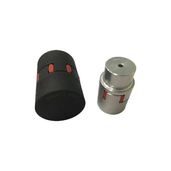
GL GE couplings are designed to transmit torque between drive and driven components with zero‑backlash via curved jaw hubs and elastomeric elements, commonly known as spiders. The combination of these components provides dampening and accommodation of misalignment. This product is available in a variety of metals, elastomers and mounting configurations to meet your specific needs. GL GS couplings suitable for horizontal or vertical applications are constructed from a variety of materials, providing a torsionally flexible zero‑backlash platform optimizing the balance between inertia, coupling performance and application requirements. The machined concaved jaws provide a pocket to preload the spider legs, allowing the spiders to articulate freely while accommodating misalignment, minimizing restoring forces, dampen shock and vibration, while providing failsafe zero‑backlash torque transmission. The symmetrical relationship of the hubs allows for a variety of accessories to accommodate different shaft distances.
Product detail pictures:
Related Product Guide:
"Quality very first, Honesty as base, Sincere assistance and mutual profit" is our idea, in an effort to create consistently and pursue the excellence for Popular Design for Mct Couplings - GE Couplings, Type 1/1, 1a/1a, 1b/1b in AL/Cast/Steel – GOODLUCK , The product will supply to all over the world, such as: Jamaica, India, Tanzania, Besides strong technical strength, we also introduce advanced equipment for inspection and conduct strict management. All the staff of our company welcome friends both at home and abroad to come for visits and business on the basis of equality and mutual benefit. If you are interested in any of our items, please feel free to contact us for quotation and product details.
It can be said that this is a best producer we encountered in China in this industry, we feel lucky to work with so excellent manufacturer.
-
Best Price for Chain Conveyor Belt - A/B Serie...
-
Bottom price Double Flex Chains/Steel Bushing C...
-
Big discounting Chains - Sugar Mill Chains, an...
-
PriceList for Gear Pulley - V-Belt Pulleys per...
-

High reputation Stainless Steel Fvc Series Conv...
-

Hot sale Stainless Steel Douple Pitch Conveyor ...