Professional Design Couplings - GE Couplings, Type 1/1, 1a/1a, 1b/1b in AL/Cast/Steel – GOODLUCK
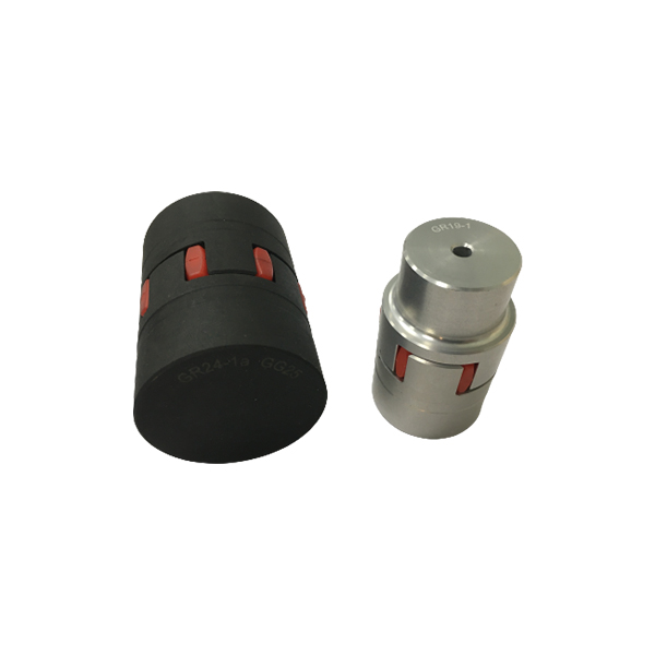
Professional Design Couplings - GE Couplings, Type 1/1, 1a/1a, 1b/1b in AL/Cast/Steel – GOODLUCK Detail:
GE COUPLINGS (AL, CAST)

|
GE(AL-H) |
|||||||||||||||||
|
ITEM |
PART |
(Nm) |
size(mm) |
||||||||||||||
|
d(min-max) |
Overall dimensions |
Set screw |
|||||||||||||||
|
92 Sh A |
98 Sh A |
64 Sh D |
L |
l1;l2 |
E |
b |
s |
DH |
dH |
D ; D1 |
N |
G |
t |
TA(Nm) |
|||
|
14 |
1a |
7.5 |
12.5 |
- |
6-16 |
35 |
11 |
13 |
10 |
1.5 |
30 |
10 |
30 |
- |
M4 |
5 |
1.5 |
|
19 |
1 |
10 |
17 |
- |
6-19 |
66 |
25 |
16 |
12 |
2 |
40 |
18 |
32 |
20 |
M5 |
10 |
2 |
|
1a |
19-24 |
40 |
|||||||||||||||
|
24 |
1 |
35 |
60 |
- |
9-24 |
78 |
30 |
18 |
14 |
2 |
55 |
27 |
40 |
24 |
M5 |
10 |
2 |
|
1a |
22-28 |
55 |
|||||||||||||||
|
28 |
1 |
95 |
160 |
- |
10-28 |
90 |
35 |
20 |
15 |
2.5 |
65 |
30 |
48 |
28 |
M8 |
15 |
10 |
|
1a |
28-38 |
65 |
|||||||||||||||
GE EN-GJL-250 ( GG 25 )
|
1 |
12-38 |
66 |
|||||||||||||||
|
38 |
1a |
190 |
325 |
405 |
38-45 |
114 |
45 |
24 |
18 |
3 |
80 |
38 |
37 |
M8 |
15 |
10 |
|
|
1b |
12-45 |
164 |
70 |
62 |
|||||||||||||
|
1 |
14-42 |
75 |
|||||||||||||||
|
42 |
1a |
265 |
450 |
560 |
42-55 |
126 |
50 |
26 |
20 |
3 |
95 |
46 |
94 |
40 |
M8 |
20 |
10 |
|
1b |
14-55 |
176 |
75 |
65 |
|||||||||||||
|
1 |
15-48 |
85 |
|||||||||||||||
|
48 |
1a |
310 |
525 |
655 |
48-60 |
140 |
56 |
28 |
21 |
3.5 |
105 |
51 |
45 |
M8 |
20 |
10 |
|
|
1b |
15-60 |
188 |
80 |
69 |
|||||||||||||
|
1 |
20-55 |
98 |
|||||||||||||||
|
55 |
1a |
410 |
685 |
825 |
55-70 |
160 |
65 |
30 |
22 |
4 |
120 |
60 |
118 |
M10 |
20 |
17 |
|
|
1b |
20-70 |
210 |
90 |
120 |
- |
||||||||||||
|
1 |
22-65 |
115 |
61 |
||||||||||||||
|
65 |
1a |
625 |
940 |
1175 |
65-80 |
185 |
75 |
35 |
26 |
4.5 |
135 |
68 |
M10 |
20 |
17 |
||
|
1b |
22-80 |
235 |
100 |
||||||||||||||
|
1 |
30-75 |
135 |
69 |
||||||||||||||
|
75 |
1a |
1280 |
1920 |
2400 |
75-95 |
210 |
85 |
40 |
30 |
5 |
160 |
80 |
1RQ |
M10 |
25 |
17 |
|
|
1b |
30-95 |
260 |
110 |
||||||||||||||
|
1 |
40-90 |
160 |
81 |
||||||||||||||
|
90 |
1a |
2400 |
3600 |
4500 |
90-110 |
245 |
100 |
45 |
34 |
5.5 |
200 |
100 |
M12 |
30 |
40 |
||
|
1b |
40-110 |
295 |
125 |
GE EN-GJL-400-15 ( GGg 40 )
|
100 |
1 |
3300 |
4950 |
6185 |
50-115 |
270 |
110 |
50 |
38 |
6 |
225 |
113 |
180 |
89 |
M12 |
30 |
40 |
|
110 |
1 |
4800 |
7200 |
9000 |
60-125 |
295 |
120 |
55 |
42 |
6.5 |
255 |
127 |
200 |
96 |
M16 |
35 |
80 |
|
125 |
1 |
6650 |
10000 |
12500 |
60-145 |
340 |
140 |
60 |
46 |
7 |
290 |
147 |
230 |
112 |
M16 |
40 |
80 |
|
140 |
1 |
8550 |
12800 |
16000 |
60-160 |
375 |
155 |
65 |
50 |
7.5 |
320 |
165 |
255 |
124 |
M20 |
45 |
140 |
|
160 |
1 |
12800 |
19200 |
24000 |
80-185 |
425 |
175 |
75 |
57 |
9 |
370 |
190 |
290 |
140 |
M20 |
50 |
140 |
|
180 |
1 |
18650 |
28000 |
35000 |
85-200 |
475 |
185 |
85 |
64 |
10.5 |
420 |
220 |
325 |
156 |
M20 |
50 |
140 |

|
GE (STEEL) |
|||||||||||||||||
|
ITEM |
PART |
(Nm) |
SIZE (mm) |
||||||||||||||
|
d(min-max) |
Overall dimensions |
Special dimensions of steel sleeve |
Set screw |
||||||||||||||
|
92 Sh A |
98 Sh A |
64 Sh D |
L |
E |
b |
s |
DH |
dh |
D;D1 |
N |
G |
t |
TA(Nm) |
||||
|
14 |
1a |
7.5 |
12.5 |
16 |
0-16 |
35 |
11 |
13 |
10 |
1.5 |
30 |
10 |
30 |
- |
M4 |
5 |
1.5 |
|
1b |
50 |
18.5 |
|||||||||||||||
|
19 |
1a |
10 |
17 |
21 |
0-25 |
66 |
25 |
16 |
12 |
2 |
40 |
18 |
40 |
M5 |
10 |
2 |
|
|
1b |
90 |
37 |
|||||||||||||||
|
24 |
1a |
35 |
60 |
75 |
0-35 |
78 |
30 |
18 |
14 |
2 |
55 |
27 |
55 |
M5 |
10 |
2 |
|
|
1b |
118 |
50 |
|||||||||||||||
|
28 |
1a |
95 |
160 |
200 |
0-40 |
90 |
35 |
20 |
15 |
2.5 |
65 |
30 |
65 |
- |
M8 |
15 |
10 |
|
1b |
140 |
60 |
|||||||||||||||
|
38 |
1 |
190 |
325 |
405 |
0-48 |
114 |
45 |
24 |
18 |
3 |
80 |
38 |
70 |
27 |
M8 |
15 |
10 |
|
1b |
164 |
70 |
85 |
- |
|||||||||||||
|
42 |
1 |
265 |
450 |
560 |
0-55 |
126 |
50 |
26 |
20 |
3 |
95 |
46 |
85 |
28 |
M8 |
20 |
10 |
|
1b |
176 |
75 |
95 |
- |
|||||||||||||
|
48 |
1 |
310 |
525 |
655 |
0-62 |
140 |
56 |
28 |
21 |
3.5 |
105 |
51 |
95 |
32 |
M8 |
20 |
10 |
|
1b |
188 |
80 |
105 |
- |
|||||||||||||
|
55 |
1 |
410 |
685 |
825 |
0-74 |
160 |
65 |
30 |
22 |
4 |
120 |
60 |
110 |
37 |
M10 |
20 |
17 |
|
1b |
210 |
90 |
120 |
- |
|||||||||||||
|
65 |
1 |
625 |
940 |
1175 |
0-80 |
185 |
75 |
35 |
26 |
4.5 |
135 |
68 |
115 |
47 |
M10 |
20 |
17 |
|
1b |
235 |
100 |
135 |
- |
|||||||||||||
|
75 |
1 |
1280 |
1920 |
2400 |
0-95 |
210 |
85 |
40 |
30 |
5 |
160 |
80 |
135 |
53 |
M10 |
25 |
17 |
|
1b |
260 |
110 |
160 |
- |
|||||||||||||
|
90 |
1 |
2400 |
3600 |
4500 |
0-110 |
245 |
100 |
45 |
34 |
5.5 |
200 |
100 |
160 |
62 |
M12 |
30 |
40 |
|
1b |
295 |
125 |
200 |
- |
|||||||||||||

GE(GG25)
|
ITEM |
TB |
size(mm) |
Mounting screw of shaft sleeve |
|||||||||||
|
l1;l2 |
E |
S |
b |
L |
N |
DH |
D1 |
dH |
Specification |
length |
number |
TA (Nm) |
||
|
24 |
1008 |
23 |
18 |
2.0 |
14 |
64 |
一 |
55 |
55 |
27 |
1/4 |
13 |
2 |
5.7 |
|
28 |
1108 |
23 |
20 |
2.5 |
15 |
66 |
一 |
65 |
65 |
30 |
1/4” |
13 |
2 |
5.7 |
|
38 |
1108 |
23 |
24 |
3.0 |
18 |
70 |
15 |
80 |
78 |
38 |
1/4” |
13 |
2 |
5.7 |
|
42 |
1610 |
26 |
26 |
3.0 |
20 |
78 |
16 |
95 |
94 |
46 |
3/8” |
16 |
2 |
20 |
|
48 |
1615 |
39 |
28 |
3.5 |
21 |
106 |
28 |
105 |
104 |
51 |
3/8“ |
16 |
2 |
20 |
|
55 |
2012 |
33 |
30 |
4.0 |
22 |
96 |
20 |
120 |
118 |
60 |
7/16” |
22 |
2 |
31 |
|
65 |
2012 |
33 |
35 |
4.5 |
26 |
101 |
19 |
135 |
115 |
68 |
7/16” |
22 |
2 |
31 |
|
2517 |
1/2” |
25 |
49 |
|||||||||||
|
75 |
. 3020 |
52 |
40 |
5.0 |
30 |
144 |
36 |
160 |
158 |
80 |
5/8″ |
32 |
2 |
92 |
|
90 |
3020 |
52 |
45 |
5.5 |
24 |
144 |
33 |
200 |
160 |
100 |
5/8“ |
32 |
2 |
92 |
|
125 |
3535 |
90 |
60 |
147 |
1/2” |
3 |
113 |
|||||||
|
4545 |
114 |
3/4″ |
49 |
192 |
||||||||||
*ONLY FOR H TYPE *BSW SCREW
|
Cone sleeve |
|||||||||||||||||||
|
Specification |
The tolerance of finished hole diameter D1 can be H7 keyway according to DIN 6885 / 1 |
||||||||||||||||||
|
1008 |
10 |
11 |
12 |
14 |
16 |
18 |
19 |
20 |
22 |
24 |
25 |
||||||||
|
1108 |
10 |
11 |
12 |
14 |
16 |
18 |
19 |
20 |
22 |
24 |
25 |
28* |
|||||||
|
1610 |
14 |
16 |
18 |
19 |
20 |
22 |
24 |
25 |
28 |
30 |
32 |
35 |
38 |
40 |
42* |
||||
|
1615 |
14 |
16 |
18 |
19 |
20 |
22 |
24 |
25 |
28 |
30 |
32 |
35 |
38 |
40 |
42* |
||||
|
2012 |
14 |
16 |
18 |
19 |
20 |
22 |
24 |
25 |
28 |
30 |
32 |
35 |
38 |
40 |
42 |
45 |
48 |
50 |
|
|
2517 |
16 |
18 |
19 |
20 |
22 |
24 |
25 |
28 |
30 |
32 |
35 |
38 |
40 |
42 |
45 |
48 |
50 |
55 |
60 |
|
3020 |
25 |
28 |
30 |
35 |
38 |
40 |
42 |
45 |
48 |
50 |
55 |
60 |
65 |
70 |
75 |
||||
|
3535 |
35 |
38 |
40 |
42 |
45 |
48 |
50 |
55 |
60 |
65 |
70 |
75 |
80 |
85 |
90 |
||||
|
4545 |
55 |
60 |
65 |
70 |
75 |
80 |
85 |
90 |
95 |
100 |
105 |
110 |
|||||||
GL GE couplings are designed to transmit torque between drive and driven components with zero‑backlash via curved jaw hubs and elastomeric elements, commonly known as spiders. The combination of these components provides dampening and accommodation of misalignment. This product is available in a variety of metals, elastomers and mounting configurations to meet your specific needs. GL GS couplings suitable for horizontal or vertical applications are constructed from a variety of materials, providing a torsionally flexible zero‑backlash platform optimizing the balance between inertia, coupling performance and application requirements. The machined concaved jaws provide a pocket to preload the spider legs, allowing the spiders to articulate freely while accommodating misalignment, minimizing restoring forces, dampen shock and vibration, while providing failsafe zero‑backlash torque transmission. The symmetrical relationship of the hubs allows for a variety of accessories to accommodate different shaft distances.
Product detail pictures:
Related Product Guide:
Adhering for the theory of "quality, services, performance and growth", we have received trusts and praises from domestic and worldwide shopper for Professional Design Couplings - GE Couplings, Type 1/1, 1a/1a, 1b/1b in AL/Cast/Steel – GOODLUCK , The product will supply to all over the world, such as: Leicester, Myanmar, Ecuador, Customer's satisfaction is always our quest, creating value for customers is always our duty, a long term mutual-beneficial business relationship is what we are doing for. We are an absolutely reliable partner for you in China. Of course, other services, like consulting, can be offered too.
 By Gemma from Sudan - 2017.10.27 12:12
The customer service staff is very patient and has a positive and progressive attitude to our interest, so that we can have a comprehensive understanding of the product and finally we reached an agreement, thanks!
By Eric from Estonia - 2018.06.26 19:27
-
High Quality Stainless Steel Sprockets - Ball ...
-
Manufactur standard Chain Drive Live Roller Con...
-
Trending Products Small Drive Chain - Leaf Cha...
-
Discountable price 630 Motorcycle Chain - Suga...
-
Good Wholesale Vendors Chain Leaf - Drop-Forge...
-
2021 Good Quality Stainless Steel Conveyor Chai...