Quality Inspection for Rm Couplings - GE Couplings, Type 1/1, 1a/1a, 1b/1b in AL/Cast/Steel – GOODLUCK
Quality Inspection for Rm Couplings - GE Couplings, Type 1/1, 1a/1a, 1b/1b in AL/Cast/Steel – GOODLUCK Detail:
GE COUPLINGS (AL, CAST)

|
GE(AL-H) |
|||||||||||||||||
|
ITEM |
PART |
(Nm) |
size(mm) |
||||||||||||||
|
d(min-max) |
Overall dimensions |
Set screw |
|||||||||||||||
|
92 Sh A |
98 Sh A |
64 Sh D |
L |
l1;l2 |
E |
b |
s |
DH |
dH |
D ; D1 |
N |
G |
t |
TA(Nm) |
|||
|
14 |
1a |
7.5 |
12.5 |
- |
6-16 |
35 |
11 |
13 |
10 |
1.5 |
30 |
10 |
30 |
- |
M4 |
5 |
1.5 |
|
19 |
1 |
10 |
17 |
- |
6-19 |
66 |
25 |
16 |
12 |
2 |
40 |
18 |
32 |
20 |
M5 |
10 |
2 |
|
1a |
19-24 |
40 |
|||||||||||||||
|
24 |
1 |
35 |
60 |
- |
9-24 |
78 |
30 |
18 |
14 |
2 |
55 |
27 |
40 |
24 |
M5 |
10 |
2 |
|
1a |
22-28 |
55 |
|||||||||||||||
|
28 |
1 |
95 |
160 |
- |
10-28 |
90 |
35 |
20 |
15 |
2.5 |
65 |
30 |
48 |
28 |
M8 |
15 |
10 |
|
1a |
28-38 |
65 |
|||||||||||||||
GE EN-GJL-250 ( GG 25 )
|
1 |
12-38 |
66 |
|||||||||||||||
|
38 |
1a |
190 |
325 |
405 |
38-45 |
114 |
45 |
24 |
18 |
3 |
80 |
38 |
37 |
M8 |
15 |
10 |
|
|
1b |
12-45 |
164 |
70 |
62 |
|||||||||||||
|
1 |
14-42 |
75 |
|||||||||||||||
|
42 |
1a |
265 |
450 |
560 |
42-55 |
126 |
50 |
26 |
20 |
3 |
95 |
46 |
94 |
40 |
M8 |
20 |
10 |
|
1b |
14-55 |
176 |
75 |
65 |
|||||||||||||
|
1 |
15-48 |
85 |
|||||||||||||||
|
48 |
1a |
310 |
525 |
655 |
48-60 |
140 |
56 |
28 |
21 |
3.5 |
105 |
51 |
45 |
M8 |
20 |
10 |
|
|
1b |
15-60 |
188 |
80 |
69 |
|||||||||||||
|
1 |
20-55 |
98 |
|||||||||||||||
|
55 |
1a |
410 |
685 |
825 |
55-70 |
160 |
65 |
30 |
22 |
4 |
120 |
60 |
118 |
M10 |
20 |
17 |
|
|
1b |
20-70 |
210 |
90 |
120 |
- |
||||||||||||
|
1 |
22-65 |
115 |
61 |
||||||||||||||
|
65 |
1a |
625 |
940 |
1175 |
65-80 |
185 |
75 |
35 |
26 |
4.5 |
135 |
68 |
M10 |
20 |
17 |
||
|
1b |
22-80 |
235 |
100 |
||||||||||||||
|
1 |
30-75 |
135 |
69 |
||||||||||||||
|
75 |
1a |
1280 |
1920 |
2400 |
75-95 |
210 |
85 |
40 |
30 |
5 |
160 |
80 |
1RQ |
M10 |
25 |
17 |
|
|
1b |
30-95 |
260 |
110 |
||||||||||||||
|
1 |
40-90 |
160 |
81 |
||||||||||||||
|
90 |
1a |
2400 |
3600 |
4500 |
90-110 |
245 |
100 |
45 |
34 |
5.5 |
200 |
100 |
M12 |
30 |
40 |
||
|
1b |
40-110 |
295 |
125 |
GE EN-GJL-400-15 ( GGg 40 )
|
100 |
1 |
3300 |
4950 |
6185 |
50-115 |
270 |
110 |
50 |
38 |
6 |
225 |
113 |
180 |
89 |
M12 |
30 |
40 |
|
110 |
1 |
4800 |
7200 |
9000 |
60-125 |
295 |
120 |
55 |
42 |
6.5 |
255 |
127 |
200 |
96 |
M16 |
35 |
80 |
|
125 |
1 |
6650 |
10000 |
12500 |
60-145 |
340 |
140 |
60 |
46 |
7 |
290 |
147 |
230 |
112 |
M16 |
40 |
80 |
|
140 |
1 |
8550 |
12800 |
16000 |
60-160 |
375 |
155 |
65 |
50 |
7.5 |
320 |
165 |
255 |
124 |
M20 |
45 |
140 |
|
160 |
1 |
12800 |
19200 |
24000 |
80-185 |
425 |
175 |
75 |
57 |
9 |
370 |
190 |
290 |
140 |
M20 |
50 |
140 |
|
180 |
1 |
18650 |
28000 |
35000 |
85-200 |
475 |
185 |
85 |
64 |
10.5 |
420 |
220 |
325 |
156 |
M20 |
50 |
140 |

|
GE (STEEL) |
|||||||||||||||||
|
ITEM |
PART |
(Nm) |
SIZE (mm) |
||||||||||||||
|
d(min-max) |
Overall dimensions |
Special dimensions of steel sleeve |
Set screw |
||||||||||||||
|
92 Sh A |
98 Sh A |
64 Sh D |
L |
E |
b |
s |
DH |
dh |
D;D1 |
N |
G |
t |
TA(Nm) |
||||
|
14 |
1a |
7.5 |
12.5 |
16 |
0-16 |
35 |
11 |
13 |
10 |
1.5 |
30 |
10 |
30 |
- |
M4 |
5 |
1.5 |
|
1b |
50 |
18.5 |
|||||||||||||||
|
19 |
1a |
10 |
17 |
21 |
0-25 |
66 |
25 |
16 |
12 |
2 |
40 |
18 |
40 |
M5 |
10 |
2 |
|
|
1b |
90 |
37 |
|||||||||||||||
|
24 |
1a |
35 |
60 |
75 |
0-35 |
78 |
30 |
18 |
14 |
2 |
55 |
27 |
55 |
M5 |
10 |
2 |
|
|
1b |
118 |
50 |
|||||||||||||||
|
28 |
1a |
95 |
160 |
200 |
0-40 |
90 |
35 |
20 |
15 |
2.5 |
65 |
30 |
65 |
- |
M8 |
15 |
10 |
|
1b |
140 |
60 |
|||||||||||||||
|
38 |
1 |
190 |
325 |
405 |
0-48 |
114 |
45 |
24 |
18 |
3 |
80 |
38 |
70 |
27 |
M8 |
15 |
10 |
|
1b |
164 |
70 |
85 |
- |
|||||||||||||
|
42 |
1 |
265 |
450 |
560 |
0-55 |
126 |
50 |
26 |
20 |
3 |
95 |
46 |
85 |
28 |
M8 |
20 |
10 |
|
1b |
176 |
75 |
95 |
- |
|||||||||||||
|
48 |
1 |
310 |
525 |
655 |
0-62 |
140 |
56 |
28 |
21 |
3.5 |
105 |
51 |
95 |
32 |
M8 |
20 |
10 |
|
1b |
188 |
80 |
105 |
- |
|||||||||||||
|
55 |
1 |
410 |
685 |
825 |
0-74 |
160 |
65 |
30 |
22 |
4 |
120 |
60 |
110 |
37 |
M10 |
20 |
17 |
|
1b |
210 |
90 |
120 |
- |
|||||||||||||
|
65 |
1 |
625 |
940 |
1175 |
0-80 |
185 |
75 |
35 |
26 |
4.5 |
135 |
68 |
115 |
47 |
M10 |
20 |
17 |
|
1b |
235 |
100 |
135 |
- |
|||||||||||||
|
75 |
1 |
1280 |
1920 |
2400 |
0-95 |
210 |
85 |
40 |
30 |
5 |
160 |
80 |
135 |
53 |
M10 |
25 |
17 |
|
1b |
260 |
110 |
160 |
- |
|||||||||||||
|
90 |
1 |
2400 |
3600 |
4500 |
0-110 |
245 |
100 |
45 |
34 |
5.5 |
200 |
100 |
160 |
62 |
M12 |
30 |
40 |
|
1b |
295 |
125 |
200 |
- |
|||||||||||||

GE(GG25)
|
ITEM |
TB |
size(mm) |
Mounting screw of shaft sleeve |
|||||||||||
|
l1;l2 |
E |
S |
b |
L |
N |
DH |
D1 |
dH |
Specification |
length |
number |
TA (Nm) |
||
|
24 |
1008 |
23 |
18 |
2.0 |
14 |
64 |
一 |
55 |
55 |
27 |
1/4 |
13 |
2 |
5.7 |
|
28 |
1108 |
23 |
20 |
2.5 |
15 |
66 |
一 |
65 |
65 |
30 |
1/4” |
13 |
2 |
5.7 |
|
38 |
1108 |
23 |
24 |
3.0 |
18 |
70 |
15 |
80 |
78 |
38 |
1/4” |
13 |
2 |
5.7 |
|
42 |
1610 |
26 |
26 |
3.0 |
20 |
78 |
16 |
95 |
94 |
46 |
3/8” |
16 |
2 |
20 |
|
48 |
1615 |
39 |
28 |
3.5 |
21 |
106 |
28 |
105 |
104 |
51 |
3/8“ |
16 |
2 |
20 |
|
55 |
2012 |
33 |
30 |
4.0 |
22 |
96 |
20 |
120 |
118 |
60 |
7/16” |
22 |
2 |
31 |
|
65 |
2012 |
33 |
35 |
4.5 |
26 |
101 |
19 |
135 |
115 |
68 |
7/16” |
22 |
2 |
31 |
|
2517 |
1/2” |
25 |
49 |
|||||||||||
|
75 |
. 3020 |
52 |
40 |
5.0 |
30 |
144 |
36 |
160 |
158 |
80 |
5/8″ |
32 |
2 |
92 |
|
90 |
3020 |
52 |
45 |
5.5 |
24 |
144 |
33 |
200 |
160 |
100 |
5/8“ |
32 |
2 |
92 |
|
125 |
3535 |
90 |
60 |
147 |
1/2” |
3 |
113 |
|||||||
|
4545 |
114 |
3/4″ |
49 |
192 |
||||||||||
*ONLY FOR H TYPE *BSW SCREW
|
Cone sleeve |
|||||||||||||||||||
|
Specification |
The tolerance of finished hole diameter D1 can be H7 keyway according to DIN 6885 / 1 |
||||||||||||||||||
|
1008 |
10 |
11 |
12 |
14 |
16 |
18 |
19 |
20 |
22 |
24 |
25 |
||||||||
|
1108 |
10 |
11 |
12 |
14 |
16 |
18 |
19 |
20 |
22 |
24 |
25 |
28* |
|||||||
|
1610 |
14 |
16 |
18 |
19 |
20 |
22 |
24 |
25 |
28 |
30 |
32 |
35 |
38 |
40 |
42* |
||||
|
1615 |
14 |
16 |
18 |
19 |
20 |
22 |
24 |
25 |
28 |
30 |
32 |
35 |
38 |
40 |
42* |
||||
|
2012 |
14 |
16 |
18 |
19 |
20 |
22 |
24 |
25 |
28 |
30 |
32 |
35 |
38 |
40 |
42 |
45 |
48 |
50 |
|
|
2517 |
16 |
18 |
19 |
20 |
22 |
24 |
25 |
28 |
30 |
32 |
35 |
38 |
40 |
42 |
45 |
48 |
50 |
55 |
60 |
|
3020 |
25 |
28 |
30 |
35 |
38 |
40 |
42 |
45 |
48 |
50 |
55 |
60 |
65 |
70 |
75 |
||||
|
3535 |
35 |
38 |
40 |
42 |
45 |
48 |
50 |
55 |
60 |
65 |
70 |
75 |
80 |
85 |
90 |
||||
|
4545 |
55 |
60 |
65 |
70 |
75 |
80 |
85 |
90 |
95 |
100 |
105 |
110 |
|||||||
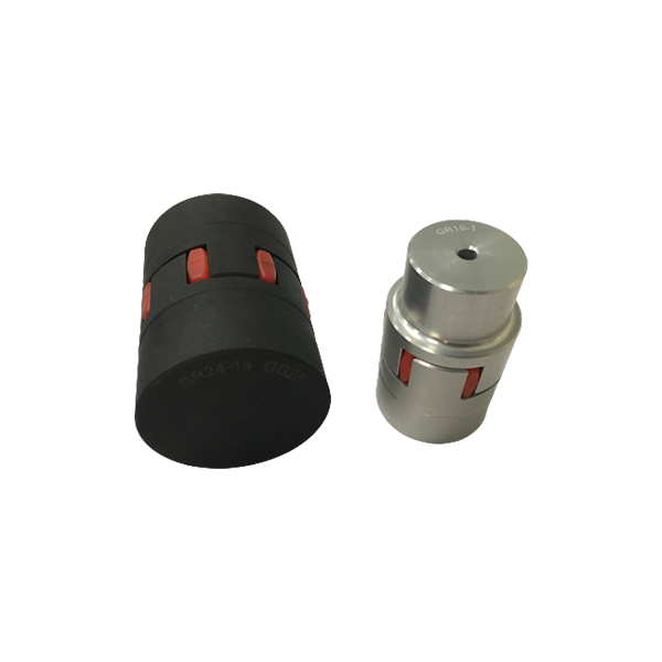
GL GE couplings are designed to transmit torque between drive and driven components with zero‑backlash via curved jaw hubs and elastomeric elements, commonly known as spiders. The combination of these components provides dampening and accommodation of misalignment. This product is available in a variety of metals, elastomers and mounting configurations to meet your specific needs. GL GS couplings suitable for horizontal or vertical applications are constructed from a variety of materials, providing a torsionally flexible zero‑backlash platform optimizing the balance between inertia, coupling performance and application requirements. The machined concaved jaws provide a pocket to preload the spider legs, allowing the spiders to articulate freely while accommodating misalignment, minimizing restoring forces, dampen shock and vibration, while providing failsafe zero‑backlash torque transmission. The symmetrical relationship of the hubs allows for a variety of accessories to accommodate different shaft distances.
Product detail pictures:
Related Product Guide:
With dependable high-quality method, fantastic standing and ideal purchaser assistance, the series of products produced by our firm are exported to many countries and regions for Quality Inspection for Rm Couplings - GE Couplings, Type 1/1, 1a/1a, 1b/1b in AL/Cast/Steel – GOODLUCK , The product will supply to all over the world, such as: Belarus, Jeddah, Bogota, Based on our guiding principle of quality is the key to development, we continually strive to exceed our customers' expectations. As such, we sincerely invite all interested companies to contact us for future cooperation, We welcome old and new customers to hold hands together for exploring and developing; For more information, please feel free to contact us. Thanks. Advanced equipment, strict quality control, customer-orientation service, initiative summary and improvement of defects and extensive industry experience enable us to guarantee more customer satisfaction and reputation which, in return, brings us more orders and benefits. If you are interested in any of our products, please feel free to contact us. Inquiry or visit to our company are warmly welcome. We sincerely hope to start a win-win and friendly partnership with you. You can see more details in our website.
This is the first business after our company establish, products and services are very satisfying, we have a good start, we hope to cooperate continuous in the future!
-
Wholesale Discount Motorcycle Chain Rivet - Su...
-
Low MOQ for Submerged Scraper Chain Conveyor -...
-
Trending Products Small Drive Chain - Leaf Cha...
-
PriceList for Stainless Steel Speed Chains - S...
-
OEM Manufacturer Stainless Steel Hss Hsc Sav Ch...
-

High Quality for Drop-Forged Pusher Dog-X458 -...