Special Design for L Couplings - GE Couplings, Type 1/1, 1a/1a, 1b/1b in AL/Cast/Steel – GOODLUCK
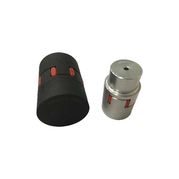
Special Design for L Couplings - GE Couplings, Type 1/1, 1a/1a, 1b/1b in AL/Cast/Steel – GOODLUCK Detail:
GE COUPLINGS (AL, CAST)

|
GE(AL-H) |
|||||||||||||||||
|
ITEM |
PART |
(Nm) |
size(mm) |
||||||||||||||
|
d(min-max) |
Overall dimensions |
Set screw |
|||||||||||||||
|
92 Sh A |
98 Sh A |
64 Sh D |
L |
l1;l2 |
E |
b |
s |
DH |
dH |
D ; D1 |
N |
G |
t |
TA(Nm) |
|||
|
14 |
1a |
7.5 |
12.5 |
- |
6-16 |
35 |
11 |
13 |
10 |
1.5 |
30 |
10 |
30 |
- |
M4 |
5 |
1.5 |
|
19 |
1 |
10 |
17 |
- |
6-19 |
66 |
25 |
16 |
12 |
2 |
40 |
18 |
32 |
20 |
M5 |
10 |
2 |
|
1a |
19-24 |
40 |
|||||||||||||||
|
24 |
1 |
35 |
60 |
- |
9-24 |
78 |
30 |
18 |
14 |
2 |
55 |
27 |
40 |
24 |
M5 |
10 |
2 |
|
1a |
22-28 |
55 |
|||||||||||||||
|
28 |
1 |
95 |
160 |
- |
10-28 |
90 |
35 |
20 |
15 |
2.5 |
65 |
30 |
48 |
28 |
M8 |
15 |
10 |
|
1a |
28-38 |
65 |
|||||||||||||||
GE EN-GJL-250 ( GG 25 )
|
1 |
12-38 |
66 |
|||||||||||||||
|
38 |
1a |
190 |
325 |
405 |
38-45 |
114 |
45 |
24 |
18 |
3 |
80 |
38 |
37 |
M8 |
15 |
10 |
|
|
1b |
12-45 |
164 |
70 |
62 |
|||||||||||||
|
1 |
14-42 |
75 |
|||||||||||||||
|
42 |
1a |
265 |
450 |
560 |
42-55 |
126 |
50 |
26 |
20 |
3 |
95 |
46 |
94 |
40 |
M8 |
20 |
10 |
|
1b |
14-55 |
176 |
75 |
65 |
|||||||||||||
|
1 |
15-48 |
85 |
|||||||||||||||
|
48 |
1a |
310 |
525 |
655 |
48-60 |
140 |
56 |
28 |
21 |
3.5 |
105 |
51 |
45 |
M8 |
20 |
10 |
|
|
1b |
15-60 |
188 |
80 |
69 |
|||||||||||||
|
1 |
20-55 |
98 |
|||||||||||||||
|
55 |
1a |
410 |
685 |
825 |
55-70 |
160 |
65 |
30 |
22 |
4 |
120 |
60 |
118 |
M10 |
20 |
17 |
|
|
1b |
20-70 |
210 |
90 |
120 |
- |
||||||||||||
|
1 |
22-65 |
115 |
61 |
||||||||||||||
|
65 |
1a |
625 |
940 |
1175 |
65-80 |
185 |
75 |
35 |
26 |
4.5 |
135 |
68 |
M10 |
20 |
17 |
||
|
1b |
22-80 |
235 |
100 |
||||||||||||||
|
1 |
30-75 |
135 |
69 |
||||||||||||||
|
75 |
1a |
1280 |
1920 |
2400 |
75-95 |
210 |
85 |
40 |
30 |
5 |
160 |
80 |
1RQ |
M10 |
25 |
17 |
|
|
1b |
30-95 |
260 |
110 |
||||||||||||||
|
1 |
40-90 |
160 |
81 |
||||||||||||||
|
90 |
1a |
2400 |
3600 |
4500 |
90-110 |
245 |
100 |
45 |
34 |
5.5 |
200 |
100 |
M12 |
30 |
40 |
||
|
1b |
40-110 |
295 |
125 |
GE EN-GJL-400-15 ( GGg 40 )
|
100 |
1 |
3300 |
4950 |
6185 |
50-115 |
270 |
110 |
50 |
38 |
6 |
225 |
113 |
180 |
89 |
M12 |
30 |
40 |
|
110 |
1 |
4800 |
7200 |
9000 |
60-125 |
295 |
120 |
55 |
42 |
6.5 |
255 |
127 |
200 |
96 |
M16 |
35 |
80 |
|
125 |
1 |
6650 |
10000 |
12500 |
60-145 |
340 |
140 |
60 |
46 |
7 |
290 |
147 |
230 |
112 |
M16 |
40 |
80 |
|
140 |
1 |
8550 |
12800 |
16000 |
60-160 |
375 |
155 |
65 |
50 |
7.5 |
320 |
165 |
255 |
124 |
M20 |
45 |
140 |
|
160 |
1 |
12800 |
19200 |
24000 |
80-185 |
425 |
175 |
75 |
57 |
9 |
370 |
190 |
290 |
140 |
M20 |
50 |
140 |
|
180 |
1 |
18650 |
28000 |
35000 |
85-200 |
475 |
185 |
85 |
64 |
10.5 |
420 |
220 |
325 |
156 |
M20 |
50 |
140 |

|
GE (STEEL) |
|||||||||||||||||
|
ITEM |
PART |
(Nm) |
SIZE (mm) |
||||||||||||||
|
d(min-max) |
Overall dimensions |
Special dimensions of steel sleeve |
Set screw |
||||||||||||||
|
92 Sh A |
98 Sh A |
64 Sh D |
L |
E |
b |
s |
DH |
dh |
D;D1 |
N |
G |
t |
TA(Nm) |
||||
|
14 |
1a |
7.5 |
12.5 |
16 |
0-16 |
35 |
11 |
13 |
10 |
1.5 |
30 |
10 |
30 |
- |
M4 |
5 |
1.5 |
|
1b |
50 |
18.5 |
|||||||||||||||
|
19 |
1a |
10 |
17 |
21 |
0-25 |
66 |
25 |
16 |
12 |
2 |
40 |
18 |
40 |
M5 |
10 |
2 |
|
|
1b |
90 |
37 |
|||||||||||||||
|
24 |
1a |
35 |
60 |
75 |
0-35 |
78 |
30 |
18 |
14 |
2 |
55 |
27 |
55 |
M5 |
10 |
2 |
|
|
1b |
118 |
50 |
|||||||||||||||
|
28 |
1a |
95 |
160 |
200 |
0-40 |
90 |
35 |
20 |
15 |
2.5 |
65 |
30 |
65 |
- |
M8 |
15 |
10 |
|
1b |
140 |
60 |
|||||||||||||||
|
38 |
1 |
190 |
325 |
405 |
0-48 |
114 |
45 |
24 |
18 |
3 |
80 |
38 |
70 |
27 |
M8 |
15 |
10 |
|
1b |
164 |
70 |
85 |
- |
|||||||||||||
|
42 |
1 |
265 |
450 |
560 |
0-55 |
126 |
50 |
26 |
20 |
3 |
95 |
46 |
85 |
28 |
M8 |
20 |
10 |
|
1b |
176 |
75 |
95 |
- |
|||||||||||||
|
48 |
1 |
310 |
525 |
655 |
0-62 |
140 |
56 |
28 |
21 |
3.5 |
105 |
51 |
95 |
32 |
M8 |
20 |
10 |
|
1b |
188 |
80 |
105 |
- |
|||||||||||||
|
55 |
1 |
410 |
685 |
825 |
0-74 |
160 |
65 |
30 |
22 |
4 |
120 |
60 |
110 |
37 |
M10 |
20 |
17 |
|
1b |
210 |
90 |
120 |
- |
|||||||||||||
|
65 |
1 |
625 |
940 |
1175 |
0-80 |
185 |
75 |
35 |
26 |
4.5 |
135 |
68 |
115 |
47 |
M10 |
20 |
17 |
|
1b |
235 |
100 |
135 |
- |
|||||||||||||
|
75 |
1 |
1280 |
1920 |
2400 |
0-95 |
210 |
85 |
40 |
30 |
5 |
160 |
80 |
135 |
53 |
M10 |
25 |
17 |
|
1b |
260 |
110 |
160 |
- |
|||||||||||||
|
90 |
1 |
2400 |
3600 |
4500 |
0-110 |
245 |
100 |
45 |
34 |
5.5 |
200 |
100 |
160 |
62 |
M12 |
30 |
40 |
|
1b |
295 |
125 |
200 |
- |
|||||||||||||

GE(GG25)
|
ITEM |
TB |
size(mm) |
Mounting screw of shaft sleeve |
|||||||||||
|
l1;l2 |
E |
S |
b |
L |
N |
DH |
D1 |
dH |
Specification |
length |
number |
TA (Nm) |
||
|
24 |
1008 |
23 |
18 |
2.0 |
14 |
64 |
一 |
55 |
55 |
27 |
1/4 |
13 |
2 |
5.7 |
|
28 |
1108 |
23 |
20 |
2.5 |
15 |
66 |
一 |
65 |
65 |
30 |
1/4” |
13 |
2 |
5.7 |
|
38 |
1108 |
23 |
24 |
3.0 |
18 |
70 |
15 |
80 |
78 |
38 |
1/4” |
13 |
2 |
5.7 |
|
42 |
1610 |
26 |
26 |
3.0 |
20 |
78 |
16 |
95 |
94 |
46 |
3/8” |
16 |
2 |
20 |
|
48 |
1615 |
39 |
28 |
3.5 |
21 |
106 |
28 |
105 |
104 |
51 |
3/8“ |
16 |
2 |
20 |
|
55 |
2012 |
33 |
30 |
4.0 |
22 |
96 |
20 |
120 |
118 |
60 |
7/16” |
22 |
2 |
31 |
|
65 |
2012 |
33 |
35 |
4.5 |
26 |
101 |
19 |
135 |
115 |
68 |
7/16” |
22 |
2 |
31 |
|
2517 |
1/2” |
25 |
49 |
|||||||||||
|
75 |
. 3020 |
52 |
40 |
5.0 |
30 |
144 |
36 |
160 |
158 |
80 |
5/8″ |
32 |
2 |
92 |
|
90 |
3020 |
52 |
45 |
5.5 |
24 |
144 |
33 |
200 |
160 |
100 |
5/8“ |
32 |
2 |
92 |
|
125 |
3535 |
90 |
60 |
147 |
1/2” |
3 |
113 |
|||||||
|
4545 |
114 |
3/4″ |
49 |
192 |
||||||||||
*ONLY FOR H TYPE *BSW SCREW
|
Cone sleeve |
|||||||||||||||||||
|
Specification |
The tolerance of finished hole diameter D1 can be H7 keyway according to DIN 6885 / 1 |
||||||||||||||||||
|
1008 |
10 |
11 |
12 |
14 |
16 |
18 |
19 |
20 |
22 |
24 |
25 |
||||||||
|
1108 |
10 |
11 |
12 |
14 |
16 |
18 |
19 |
20 |
22 |
24 |
25 |
28* |
|||||||
|
1610 |
14 |
16 |
18 |
19 |
20 |
22 |
24 |
25 |
28 |
30 |
32 |
35 |
38 |
40 |
42* |
||||
|
1615 |
14 |
16 |
18 |
19 |
20 |
22 |
24 |
25 |
28 |
30 |
32 |
35 |
38 |
40 |
42* |
||||
|
2012 |
14 |
16 |
18 |
19 |
20 |
22 |
24 |
25 |
28 |
30 |
32 |
35 |
38 |
40 |
42 |
45 |
48 |
50 |
|
|
2517 |
16 |
18 |
19 |
20 |
22 |
24 |
25 |
28 |
30 |
32 |
35 |
38 |
40 |
42 |
45 |
48 |
50 |
55 |
60 |
|
3020 |
25 |
28 |
30 |
35 |
38 |
40 |
42 |
45 |
48 |
50 |
55 |
60 |
65 |
70 |
75 |
||||
|
3535 |
35 |
38 |
40 |
42 |
45 |
48 |
50 |
55 |
60 |
65 |
70 |
75 |
80 |
85 |
90 |
||||
|
4545 |
55 |
60 |
65 |
70 |
75 |
80 |
85 |
90 |
95 |
100 |
105 |
110 |
|||||||
GL GE couplings are designed to transmit torque between drive and driven components with zero‑backlash via curved jaw hubs and elastomeric elements, commonly known as spiders. The combination of these components provides dampening and accommodation of misalignment. This product is available in a variety of metals, elastomers and mounting configurations to meet your specific needs. GL GS couplings suitable for horizontal or vertical applications are constructed from a variety of materials, providing a torsionally flexible zero‑backlash platform optimizing the balance between inertia, coupling performance and application requirements. The machined concaved jaws provide a pocket to preload the spider legs, allowing the spiders to articulate freely while accommodating misalignment, minimizing restoring forces, dampen shock and vibration, while providing failsafe zero‑backlash torque transmission. The symmetrical relationship of the hubs allows for a variety of accessories to accommodate different shaft distances.
Product detail pictures:
Related Product Guide:
We normally believe that one's character decides products' quality, the details decides products' high-quality ,while using the REALISTIC,EFFICIENT AND INNOVATIVE staff spirit for Special Design for L Couplings - GE Couplings, Type 1/1, 1a/1a, 1b/1b in AL/Cast/Steel – GOODLUCK , The product will supply to all over the world, such as: Tanzania, Manchester, Greenland, Please really feel free to send us your requirements and we'll respond to you asap. We have got a professional engineering group to serve for your just about every detailed needs. Cost-free samples could be sent for you personally to understand much more information. In an effort to meet your requires, please really feel free to make contact with us. You may send us emails and contact us directly. Moreover, we welcome visits to our factory from around the globe for much better recognizing of our organization. nd items. In our trade with merchants of numerous countries, we usually adhere for the principle of equality and mutual benefit. It is actually our hope to market, by joint efforts, each trade and friendship to our mutual advantage. We look forward to getting your inquiries.
It can be said that this is a best producer we encountered in China in this industry, we feel lucky to work with so excellent manufacturer.
-
Bottom price Stainless Steel Fv Series Conveyor...
-
OEM Supply Stainless Steel Flat Top Chains - S...
-
factory low price Orange Motorcycle Chain - Ca...
-
Hot Sale for Power Transmission Chain Drive - ...
-
Chinese Professional Metal Sprockets - Double ...
-
Factory Promotional Chain Sprocket - Stainless...